As I got home to take the boys out to dinner, I saw a pile of holiday deliveries at the door, including a rather hefty USPS LFR (Large flat rate) box from QU-BD!
Now that the boys are fed, time to unbox the QU-BD for a first look! 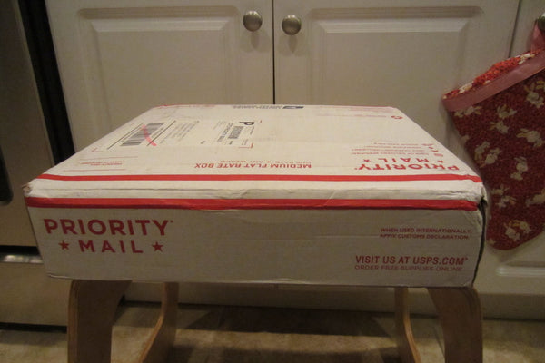
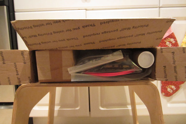


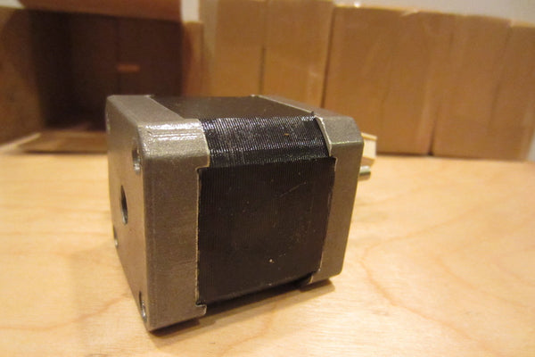


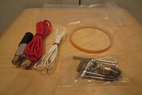

The first thing I noticed when I opened the box is the faint smell of burnt wood. It took me back to the day when I unboxed my MakerBot Thing-O-Matic kit! Roughly two years later, it's the same thrill, though at a much lower price point (about 1/7th what I paid for the ToM, iirc).
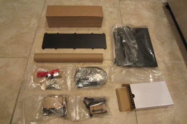
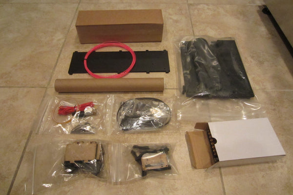
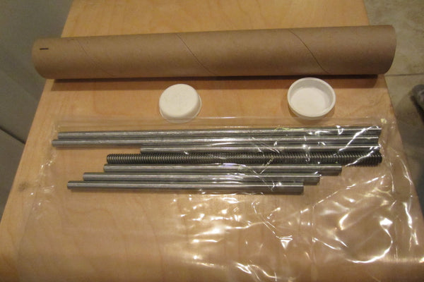
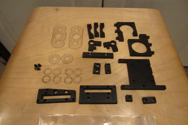
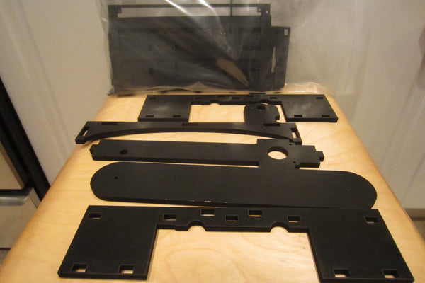
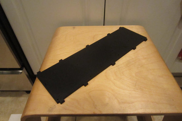
The box showed some sign of shipping stress, but the Gods of Logistics seemed to have smiled upon us, as everything looked to be in good order. The contents of the box seemed to survive the shipping fairly well. One piece of MDF had some dings, where the underlying particle board showed through, but otherwise, all the pieces looked pretty good during my initial inspection.
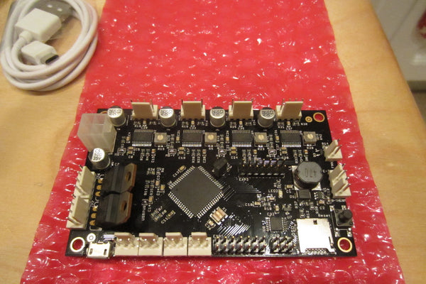
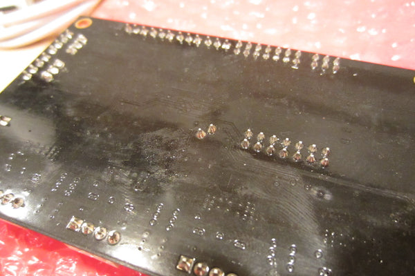
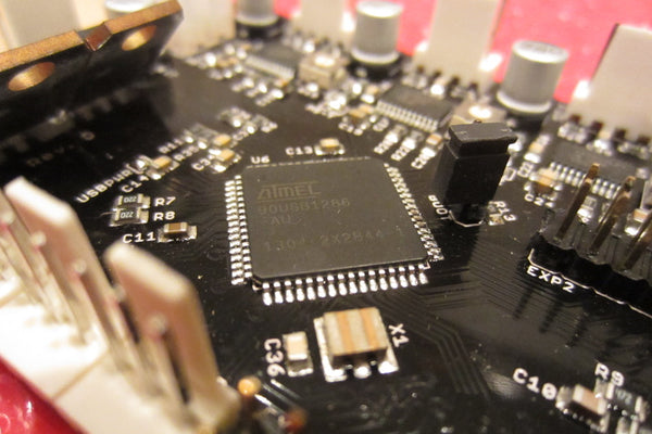
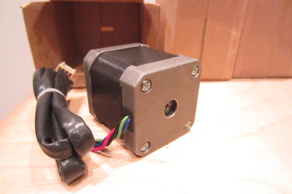
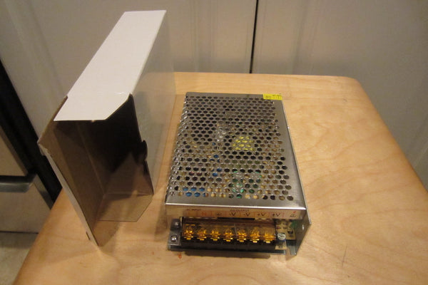
I did have a few quibbles, though. The power supply seems to lack any safety certificatoon marks; on the control PCB, there were sticky smudges and finger prints on the board (likely due to incomplete washing) and the FET's were bent down to fit the packaging (probably harmless, but devices manufacturers will tell you to avoid doing that). I also wish the steppers had their specification stickers on them, but that's really not a big deal.
Overall, a pretty reasonable kit for $200. I'm looking forward to putting this together soon.
Oh, BTW, if you have received or have ordered a QU-BD OneUp or TwoUp as well, drop me a line, and I'll send you a nice discount code for some filament from our store.
UPDATE 1: I have started assembling the OneUp, but am stuck building the extruder. It appears that I may be missing the basic HEM_r3.DXF piece which holds the filament drive parts together. Fortunately, I already have a 3D printer, so I was able to print a substitute part which worked after some filing (the holes were just a tad undersized).
UPDATE 2: For anyone already embarking on assembling their printers - do be careful. Some of the pieces are fragile, as evidenced by the damage during shipping. Even mine, which arrived looking well, had a piece break while I was wiping off some of the laser-cutter soot (one of the extruder mount walls); and the lower span of the YZMAIN broken when I accidentally picked up the entire thing at once and applied pressure on the span.
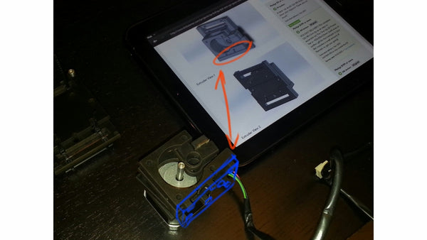
The diagram posted for the extruder in the Kickstarter Update 23 does not match up with the the way it's shown on the YouTube video shot by QU-BD's local customer. I think you need to swap the two walls with the clearances for the motor, and have the button head on the side away from the motor. Otherwise, the button head bumps up against the motor. (See John Seward's YouTube for some more info.)
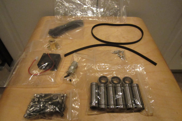
BTW, the BOM at the source file directory doesn't call out the different laser cut pieces; and seems to be missing a few more pieces (washers, mostly, and some springs, possibly for leveling the bed?). I guess the cable harness seen with the prototype unit in the launch video is no longer part of the production release?
The fan I received does not have a long enough cord, and I think had the wrong type connector to mount to the Printboard clone.
The laser-cut rail-discs for the belts are undersized for the bearing that comes with our kit. It looks like the prototype units had smaller bearings?
I'm just one step away from being done with the mechanical assembly -- I just couldn't figure out how the heck to connect the belt to the extruder...
Stay tuned -- I'll be posting more here as I go.
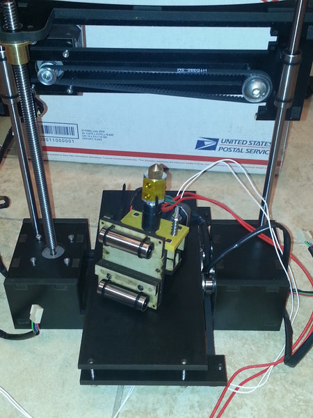
UPDATE 3: It's running! Sort of. I still am not sure about how to affix the extruder carriage to the belt, so I've temporarily lashed it with a twist-tie. After several false attempts getting the USB comm drivers to work, I have it up and running with Repetier Host!
UPDATE 4: I have more permanently attached the extruder to the belt (with super glue) and retightened all the pulleys. Here are some videos of the first few prints -- I still have to get the settings all dialed in.
The weight of the extruder makes the carriage sag a bit to the right. I leveled the print bed so that the gap is consistent across the four corners.
At "normal" speeds, I was having some extrusion problems -- I think the nozzle is not maintaining temperature -- possibly needing an adjustment to the PID parameters for the hot end, or needing the cooling fan (to have an increased steady-state heating of the heater cartridge), and/or adding insulation to the heating block.
By the way, I had just reused an existing Repetier-Host install that I had for a different printer (a Deezmaker BukoBot). I then stripped the start gcode to remove the homing and bed heating commands, and started the print job from the corner (instead of the center).
With the nozzle where I want, I issued a "G92 X0 Y0 Z0" command to reset the coordinates. The, after each print, if I wanted to go back to the same starting point, I issue a "G1 X0 Y0 Z0".
UPDATE 5: I have measured the Y travel as 83 mm. It's physically constrained by the tab on the Y-bed hitting the MDF front and back walls of the base.
I have measured the X travel as 100 mm. By orienting the extruder nozzle more carefully, you might be able to get another 2 or 3 mm.
The Z height will depend, in part, on how high your print bed started. I get roughly 115 mm of Z travel, and the bed can theoretically go down about 10 mm (assuming you switch to small screws instead of the long screws and leveling springs).
BTW, the One Up, not having any endstops in the design, is easy to crash with G-code moves. I have a divot on my print bed from not having reset the coordinates. Do be careful!
UPDATE 6: The extruder cooling fan, from what I've seen on the Kickstarter launch video, mount with a L bracket that is captured by one of the screws for the extruder stepper motor.
When I tried to use that bracket in the same way, I could not get the screw to engage its threads on the stepper motor housing. As a workaround, I just took some solid 22 AWG wire and looped it under the screw head, and tightened down. I did that on two sides of the stepper, and it seems to work okay.
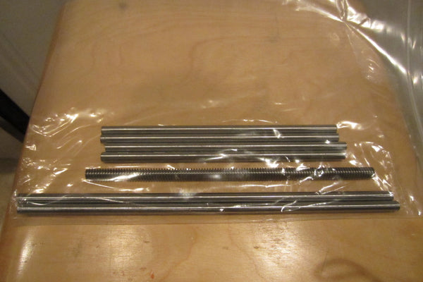
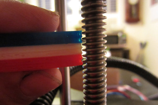
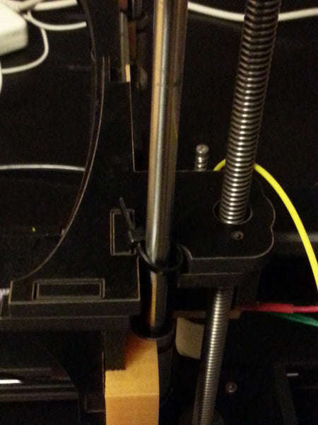
UPDATE 7: There is a significant Z wobble with my One Up. Looking at the Z-screw during fast Z travels, I can see that the thread screw is a bit bowed. I am not sure if it was already that way from the beginning, or if I caused that by crashing the gantry against the upper limit (I had the cable bundle between the gantry and the handle - that definitely didn't help). (Correction: it's Z-banding or z-ribbing.)
UPDATE 8: A number of users have uploaded replacement parts STL's to Thingiverse, and CorySTG on fabric8r.com has also uploaded IGES conversions of the laser-cut parts. Hopefully, some of this is useful for people that need to reprint replacement parts on their own.
UPDATE 9: MacAttack on Fabric8r.com has reported that the stepper shaft and the Z nut alignment are significantly off. When I was assembling the One Up, I noticed that the smooth rod's location relative to the notch in the top-plate seemed a little odd. When I look at it now, I can confirm that the Z-screw to Z-rod distance is not consistent with the Z-nut to Z-bearing distance, causing the Z-screw to be tilted out by a little bit.
Looking at the source DXF files, it's clear that the Z-rod and Z-screw locations are supposed to be aligned in the Y direction. From the looks of it, the Z bearing needs to be shimmed out by 3 mm's.


UPDATE 10: I have uploaded a bearing spacer to Thingiverse (http://www.thingiverse.com/thing:213752) which places the Z-bearings closer to the ideal location. The Z-banding that I was getting before seems to be diminished, although I will need to do more prints to be sure. The carriage, unfortunately, still sags down on the right.
UPDATE 11: I have updated the bearing spacer upgrade (http://www.thingiverse.com/thing:213752) so that the spacer hugs the gantry's main MDF board. The spacer has no wobble. There is still some sagging of the gantry because the linear bearing is still attached with zip-ties and have some give -- but the sagging is much less than before.


You don't absolutely have to have this part to begin assembling and using this printer -- you could print the part after assembling the printer, and then retrofitting the printer with it. But, if you still would rather have the part pre-printed for you, please follow this link.
UPDATE 12: Not sure if this is a firmware issue, or if perhaps it's just my board - but I cannot get the microSD interface to work with the microSD cards that I have. When I send the M21/M20 commands to initialize the SD card interface and request a list of files, I get an error message that the SD interface failed to initialize. I have tried it with a 2GB card, which *should* work.
BTW, there is apparently a design limitation with the PrintrBoard - the SD interface cannot work while the Y endstop is engaged. (http://my3dprinterbuild.wordpress.com/2012/09/02/printrboard-sd-card-boot-up-fix/)
UPDATE 13: It turns out the fan PWM and the SDCard hardware is fine -- they just require rebuilding the firmware as outlined here and updating the controller. Here's a not-so-great video of the fan and the SD-card working:
UPDATE 14: Just a reminder - when you use your printer, you must first manually home the bed and the nozzle, and issue a "G92 X0 Y0 Z0" command. Then run your gcode. Make sure that the gcode does not contain the G28 "seek home" command, nor the M190 "wait for heated bed" command (unless you have a heated bed, in which case you can use the M190 command).
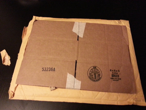
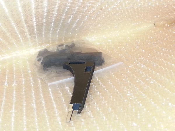
UPDATE 15: Based on the list of open issues with the parts on the OneUp, and Nathan's response to that punch-list instructing us to file a support ticket to get replacement parts, I went ahead and filed a request for parts on Jan 2. Two weeks later (without any notificationon the ticket), a first class padded envelope arrived in the mail box. Good, right?
Alas, when I opened the padded envelope, I found the replacement X-gantry top piece to be broken.

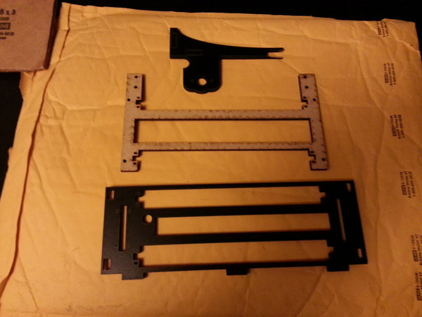
The good news is that the replacement X-gantry top piece does shifted the threaded Z-screw 3 mm closer X-gantry main piece. This will eliminate the need for the Z-bearing spacers (once I get the part in one piece):
The broken X-gantry top piece, overlaid on top of the original X-gantry top piece. You can see that with the Z-screw centered in the hole where the Z-nut mounts, the X-gantry main piece will be shifted closer to the Z-screw. This will eliminate the need for a printed spacer (seen above, printed in gold PLA).